I had been procrastinating installing solar on the motor home for a number of reasons. The rig seems unsuitable for any real boondocking but dry camping is another story. It has a 7.5kw diesel generator which, while useful, is rather noisy especially when at some Harvest Host locations. And lastly, I really didn't want to drive screws into the fiberglass roof. Based on my experience, there is a chance for cracks to form when screws are driven in.
I procrastinated ordering the panels themselves and they are now on backorder for about three weeks. They are being shipped to a friend's home in the PNW. Over the next month, I’ll be able to install everything except the panels themselves including the wiring onto the roof.
- 3x 210-watt Hi-Tec monocrystalline panels
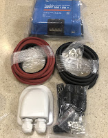
- Victron Energy SmartSolar MPPT 100/50 charge controller (3rd picture)
- 100’ 10AWG UV resistant solar cable. This will run from the panels to the shutoff
- 2x Solar Cable waterproof entry gland (only need one) (3rd picture)
- 8x MC4 connector set for 10AWG solar cable (3rd picture)
- 2x 10’ 6AWG welding cable w/10 lug connectors and shrink tubing (3rd picture)
- 3x corner and side mounts to be glued to the roof (2nd picture)
- Sikaflex-259, a 1 component, moisture-cured, polyurethane adhesive?(2nd picture)
- Solar DC isolator switch. 1000v/32amp
- 80amp circuit breaker
- Victron battery temperature sensor
The corner and side mounts will be screwed into the sides of the panels using SS hardware. The mounts will be fastened to the fiberglass roof using the Sikaflex. No drilling required. Two of the panels will be in front of the A/C starting on the drivers side of the roof and the third will be right behind to the left of the A/C.
The three panels will be wired in series. Panel specifications, Voc=24.9VDC, Isc=9.85amps. So max voltage and current into the Victron charge controller would be 74.7VDC and 9.85amps. The maximum charge current to the batteries would be 50A limited by the charge controller.
The 10AWG cable will be run from the MC4 connectors on the panels to the DC isolator switch. The estimated distance is 25’. Counting both positive and negative runs, the voltage drop over the 50’ of cable is under 1VDC. Reasonable considering the panel output voltage is around 75VDC.
The 6AWG cable will be run from the output of the charge controller, through the 80amp circuit breaker to the batteries. The voltage drop would be about 0.7VDC if the charge controller was 10’ from the batteries. 6AWG is the largest cable that the Victron 100/50 supports so the controller could be closer to the batteries. The temperature sensor replaces the power cable on the 500amp shunt for the BMV-512 battery monitor that I had installed over a year ago. The temperature and battery voltage is fed up to the battery monitor and relayed to the charge controller via Bluetooth. This allows the charge controller to modify its charging parameters depending on the battery temperature and the actual voltage at the battery terminals.
On the “average” dry camping day, we use about 240 amp-hours. These panels should keep up on most days. But we always have the diesel generator for cloudy days. At our last HH overnight, we used 175 amp-hours including some microwave and Keurig use. The majority of the power was used by the two propane furnaces with temperatures in the high 30s (°F). So we use much more power than we did with the 5th wheel RV. For now, we will continue to use the 4x flooded, 6V golf cart batteries which give us 210 amp-hours of useable capacity.


No comments:
Post a Comment