I started to lay out the DC electrical board for the front storage compartment of the RV. According to the dimensions I was given, there is 31" of open space so I have that marked off on the ¾" plywood. I'm going to lay it out and make cables using that dimension but I'll hold off on cutting the plywood until I'm actually there. The height is also unknown but I'm guessing that there is more than 16" of height in the compartment above the battery box. Time to start making cables.
This is a good comparison between the 2/0 awg on the left and 2 awg arc welding cables. The overall diameter is almost identical but the amount of actual wire and resultant current carrying capacity is dramatically different. Since the 2 awg cable wasn't labeled, I weighed the welding cable after trimming off the ends to find the weight per foot. Then looked it up in a table (on the Internet) to find the wire size. I will be using the 2 awg wire for the connections from the solar charge controller to the battery. It's kind of overkill since the maximum current is only 45 amps. But the maximum wire size supported by the charge controller is 2 awg and I just happen to have some lying around.
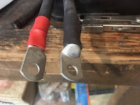
Using the hydraulic press to crimp the cables works really well. Here are my first attempts with the 2/0 awg. The shrink tubing and connectors are from ABS Alaskan. I need to work a little on my technique as I may be crimping a bit too much (it's a 12 ton press). After the insulation is removed, some anti-oxidation paste is put on the exposed copper before crimping the terminal. Special heat shrink tubing with some sort of glue is used to keep air and moisture out of the connections.
Here it is mostly done. The connections to the battery are the 250 amp catastrophic fuse aka "cat", at the lower left and the 500 amp shunt on the right. For now, I just have some 4 awg cables going to the group 24 AGM battery from the BMW sidecar rig. The same anti-oxidation paste is used on all of the screw terminals before tightening.
I have the Bogart Engineering Trimetric 2025-RV connected to the shunt and the fused side of the cat fuse. I still need to go through the setup routine to set the battery type and capacity. The Trimetric will then track usage and display percent used.
This is the 500 amp shunt. Basically a precise, very low resistance device that all DC current passes through. The Trimetric will then measure the voltage and use Ohms law to calculate the current. The short cable just goes to a bus bar to prevent having to stack all of the negative terminals on one bolt. The bus bar is also rated for 250 amps.
The solar charge controller is on the left and the 2000 watt inverter is on the right. The rotary power switch (also rated for 250 amps continuous) allows me to shut off power to the inverter and eventually the DC power to the rest of the RV. The switch is currently in the "off" position and the RV 12VDC feed will be from the opening on the lower part of the switch. N.B. The shutoff switch does not switch off the charge controller. When the solar charge controller is set to equalization, the voltage could go above 16 VDC depending on the battery temperature which could damage something. This allows you to take everything off line.
The two 50 amp circuit breakers are for the input and output of the solar charge controller. Output on top and input just below that. Note that the breakers are "tripped" with the red button so they work as switches. I still need to pick up some cable clamps that fit the knock outs on the Morningstar charge controller from the hardware store before terminating the cables. I also need some ground wire for the chassis of the inverter and the charge controller. I also ordered some cable clamps to keep the cables from moving or vibrating while traveling down the road.
I also plan to order one 100 watt, 12 volt solar panel to test the charge controller.


Very nice work Richard. Isn't the 2/0 awg more flexible than the welding cable also?
ReplyDeleteBoth the 2/0 awg and 2 awg are arc welding cables and both are fairly flexible.
DeleteReally nice work RichardM! I plan to plagiarize your setup of course, though I've no idea where I'm going to mount all the stuff as my motorhome doesn't have a nice big storage area for it that your 5th wheel has. Heck, still trying to figure out how to squeeze two 6v batteries where the one 12v resides today. Measurements say the will fit, reality will most likely be something else.
ReplyDeleteThank you. I'm happy with the way it ended up looking. Hopefully I'll just be able to cut the plywood to size and install it in the compartment.
DeleteMaybe you can come up with some sort of sliding drawer arrangement to hold the batteries. I think that they would fit the compartment and tray but servicing them and wiring them up will be a bear. The T-105 batteries have a remote fill option for adding distilled water to the individual cell. Or at least I saw a setup somewhere in a class C where they put in stacked 6V batteries.
Yep, did some more measuring and it'd be a really tight fit....a slide out tray would be nice but not sure it wouldn't take up room which is tight now. The water filler gadget would be required too....must think more on this.
DeleteI think that the length of the 6V golf cart batteries will fit the width of your tray. Though you will need to move the inverter and find a way to hold the batteries in place. The water filler would be essential.
Delete